Platform Calibration Tips
Platform calibration involves a procedure of checking the distance between the nozzle and five calibration points on the platform, and tightening/loosening the calibration screws.
It is necessary to run platform calibration before using the printer for the first time and when you encounter printing problems, such as warping or incomplete prints.
Platform calibration is not complicated and does not take much time. Always follow the instructions displayed on the screen and tighten or loosen the screws indicated in the message. Turn the screws slightly, only by a few degrees.
At the end of the procedure, the display will show the calibration results with the height values of each point.
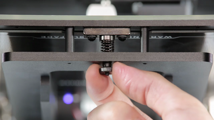
M300 Platform Calibration
In order to correct the difference in values between the center and the side calibration points, you should tighten/loosen the two platform screws placed next to the center point. If the center point value is 0.2 and one of the side points value is -0.2 (the difference equals or exceeds 0.4), you should tighten the screws, whereas you should loosen them if the center point value is -0.2 and one of the side points value is 0.2.
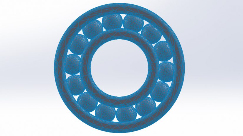
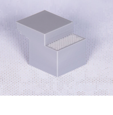
Types of Infill
The infill option determines the amount of material that will be printed within the walls of the model. This option influences the model’s durability and weight, both of which can be increased by setting a higher level of infill. However, the higher infill, the more time and material will be needed for such a print.
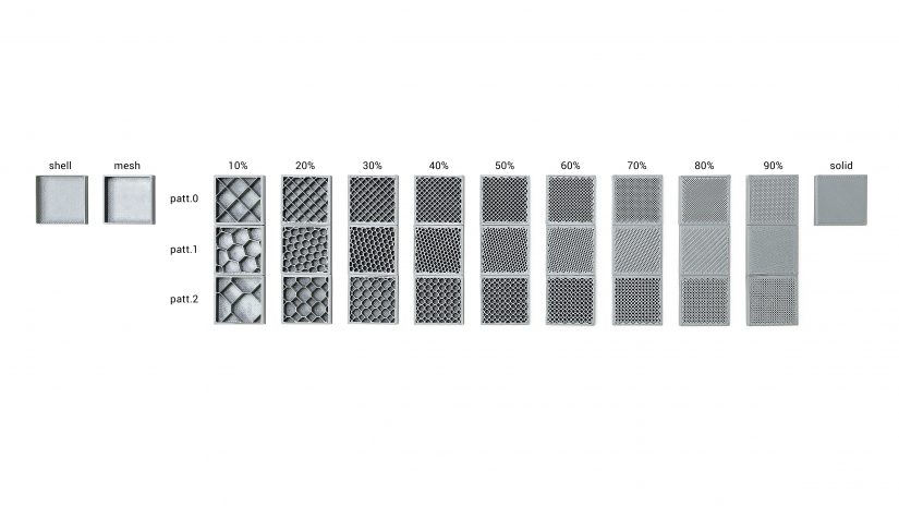
In Normal and Advanced settings in Z-SUITE, there are four types of infill to choose from: Mesh, Shell, Normal and Solid.
The model with the Mesh type will have 0% of infill, whereas the model with the Shell type will have no top and bottom surface layers (the bottom ones are optional) and 0% of infill.
Additionally, there are three patterns available within the Normal type: regular (patt. 0), honeycomb (patt. 1), and octagonal (patt. 2). Infill density can be increased by adjusting the slider (from 10 to 90%).
The Solid type gives your models 100% of infill.
Setting Proper Dimensions
Zortrax printing materials vary when it comes to their physical properties. The main thing you have to consider before the printing process is the level of shrinkage of a particular material. It can basically influence the actual size of the printed object. Usually the final object is smaller than the design. To avoid this, you have to estimate the approximate shrinkage and add from 0.2mm to 0.3mm to each dimension.
The minimum diameter of the hole must be 1mm. The minimum wall thickness is 0.8mm, whereas with the shell infill, the minimum wall thickness can be of 0.4mm.
Printing Small Objects
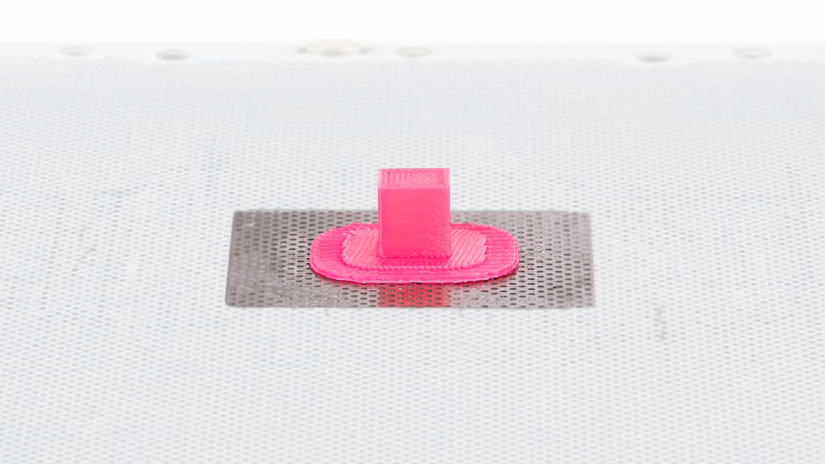
Very small objects require some additional options such as the appropriate FAN SPEED and LAYER THICKNESS settings.
Set the lowest layer thickness possible and the additional FAN SPEED to 80-100%. Also, print two or more models simultaneously so that the layers of each print have time to cool down.
Placing your model vertically is also profitable in this case.
Large Prints
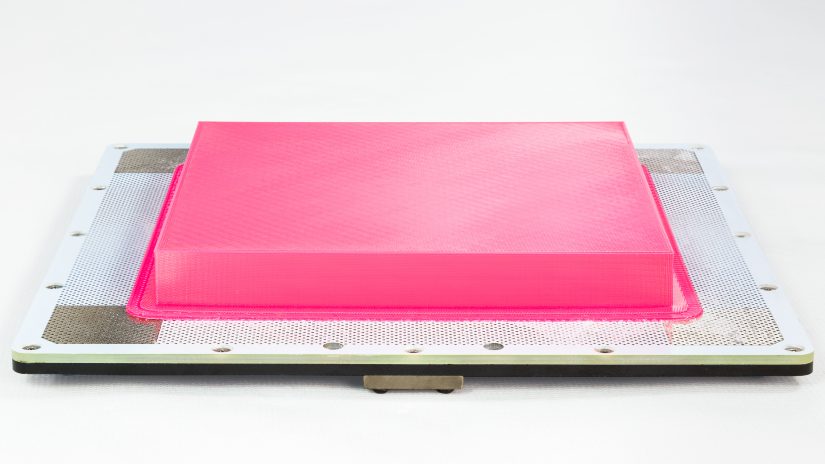
The problem of warping is frequent with large prints. Bigger models often shrink and do not stick to the platform during the printing process.
Make sure that the platform is calibrated and the printer is not exposed to drafts. Carry out Platform Maintenance, and use side covers and platform V2 with your 3D printer.
Additionally, it is better to choose low density of infill (medium or light) or, if low density is problematic, choose the mesh option. For large prints with no precise details, the optimum layer thickness is 0,19mm or 0,29mm. The FAN SPEED should be set to 0.
If you encounter warping problems, you should apply the Z-ABS juice on the perforated plate so that the models will not detach from the platform.
Removing the Support
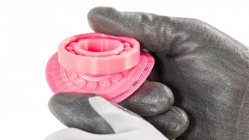
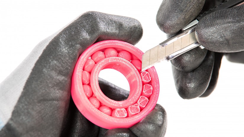
Before any attempt to remove the support structure, wear safety gloves and glasses.
At first, detach the raft by hand.
Then, remove the support using the tools from the Starter Kit: a cutting knife, a scalpel or a pair of pliers or tweezers.
If any deformed elements start to appear on the model during the printing process (e.g. hanging strands of material), the SUPPORT settings may be inadequate.
To avoid such imperfections, increase the value of the SUPPORT ANGLE. Remember that greater amount of support will be more difficult to remove. You can also increase the FAN SPEED.