The extruder is equipped with three fans – one upper and two lower. The main role of the extruder upper fan is to cool down the extruder, whereas the extruder lower fans cool down each layer of a print. Therefore, if you notice that your models melt, warp, or there are burn marks on their surface, at first check if the fans on the extruder are functioning properly. You can carry out a fan test using the option available in the Tools menu. If the blades of the fans do not spin, the fans need to be replaced. This manual shows how to replace all three extruder fans.
| The following manual shows the M200 Plus repair work. For the M300 Plus, these procedures are the same. |
Unplugging the Power Cable
Turn off the printer and unplug the power cable.
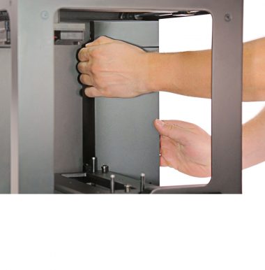
Extruder Upper Cover Removal
Detach the extruder upper cover from the extruder.
Unplugging the Extruder Cable
Detach the material guide and unplug the extruder cable.
Hotend Removal
With a 1.5mm Allen key loosen the two screws that secure the hotend and remove the hotend from the extruder.
Heater and Thermocouple Removal
With a 1.5mm Allen key loosen the two screws that secure the heater and thermocouple in the hotend. Then remove both the heater and the thermocouple from the hotend.
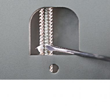
Heater and Thermocouple Removal (from the Extruder)
Remove the heater and thermocouple from the extruder block and the heat shrink tubing.
Extruder Upper Fan Replacement
Unplugging the Extruder Upper Fan Cable
Unplug the red connector from the extruder PCB. Remove the cable from the heat shrink tubing.
Unscrewing the Extruder Upper Fan
Unscrew the two screws that secure the extruder upper fan. Remove the fan.
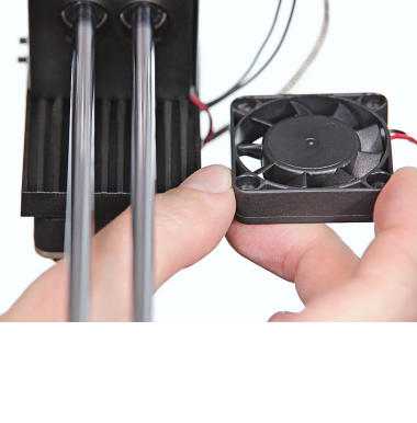
Extruder Upper Fan Assembly, part 1
Place the extruder upper fan on the heat sink next to the extruder alumium block. Secure the fan with the two screws.
Extruder Upper Fan Assembly, part 2
Pass the extruder upper fan cable through the heat shrink tubing and plug in its connector.
Extruder Lower Fan 1 Replacement
Unplugging the Extruder Lower Fan Cable
Unplug the blue connector from the extruder PCB. Remove the cable from the heat shrink tubing.
Unscrewing the Extruder Lower Fan
Unscrew the two screws that secure the extruder lower fan.
Extruder Lower Fan Removal, part 1
Separate the extruder lower fan from the heat sink and remove the distance piece.
Extruder Lower Fan Removal, part 2
Separate the extruder lower fan from the fan shroud.
Extruder Lower Fan Assembly, part 1
Put the fan shroud together with the new extruder lower fan.
Extruder Lower Fan Assembly, part 2
Place the distance piece on the extruder lower fan. Install the fan under the heat sink.
Securing the Extruder Lower Fan
Secure the extruder lower fan with the two screws.
Plugging in the Extruder Lower Fan Cable
Put the extruder lower fan cable through the heat shrink tubing and plug it in.
Extruder Lower Fan 2 Replacement
Unplugging the Extruder Lower Fan Cable
Unplug the other blue connector from the extruder PCB. Remove the cable from the heat shrink tubing.
Unscrewing the Extruder Lower Fan
Unscrew the three screws that secure the extruder lower fan.
Extruder Lower Fan Removal, part 1
Separate the extruder lower fan from the heat sink and remove the distance piece.
Extruder Lower Fan Removal, part 2
Separate the extruder lower fan from the fan shroud.
Extruder Lower Fan Assembly, part 1
Put the fan shroud together with the new extruder lower fan.
Extruder Lower Fan Assembly, part 2
Place the distance piece on the extruder lower fan. Install the fan under the heat sink.
Securing the Extruder Lower Fan
Secure the extruder lower fan with the three screws.
Plugging in the Extruder Lower Fan Cable
Put the extruder lower fan cable through the heat shrink tubing and plug it in.
Heater and Thermocouple Assembly
Put the heater and thermocouple cables through the heat shrink tubing.
Heater and Thermocouple Assembly (in the Hotend)
Insert the heater and thermocouple into the hotend and firmly tighten the two screws (using a 1.5mm Allen key).
Hotend Assembly
Insert the hotend into the extruder and tighten the two screws that secure it (using a 1.5mm Allen key).
Plugging the Extruder Cable
Plug in the extruder cable and attach the material guide to the extruder top cover.
Extruder Upper Cover Assembly
Attach the extruder upper cover to the extruder.