The extruder bearing supports extrusion by pressing the material to the extruder motor sprocket wheel during loading and the printing process. Therefore, when the material in your printer is not being extruded when loading or printing, or the sprocket wheel is making clicking sounds, the extruder bearing may be faulty and should be replaced. Follow the steps from this manual to see the correct replacement procedure.
| If the material is loaded into the extruder, unload the material using the “Material” -> “Unload material” option in the printer menu. |
| The following manual shows the M200 repair work. For the M300, these procedures are the same. |
Unplugging the Power Cable
Turn off the printer and unplug the power cable and wait a few minutes for all the capacitors to discharge.
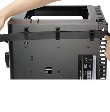
Material Guide Removal
Detach the material guide from the extruder cover. Next, separate the guide from the extruder cable.
Unplugging the Extruder Cable
Detach the extruder upper printed cover and unplug the extruder cable.
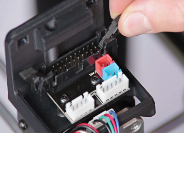
Unplugging all Cables from the Extruder PCB
Unplug all the cables from the extruder PCB.
Unscrewing the Extruder PCB
Unscrew the two screws that secure the extruder PCB using a 2mm Allen key. Remove the PCB from the extruder.
Extruder Lower Printed Cover Removal
Remove the extruder lower printed cover.
Unscrewing the Extruder Aluminum Cover
Unscrew the screws that secure the extruder aluminum cover on both sides of the extruder. Separate the cover from the extruder motor.
Unscrewing the Extruder Motor
Unscrew the four screws that secure the extruder motor.
Extruder Motor Removal
Separate the extruder motor from the extruder block.
Unscrewing the Extruder Bearing
Unscrew one screw that secures the extruder bearing.
Extruder Bearing Removal
Remove the extruder bearing using tweezers.
Extruder Bearing Assembly
Insert the new bearing into the extruder block and secure it with the screw.
Extruder Motor Assembly, part 1
Reattach the extruder motor to the extruder block.
Extruder Motor Assembly, part 2
Secure the motor with the screws. Press the motor to the right side so that the bearing rack is as close to the bearing as possible. Tighten the screws crosswise in the following order: 1-4, 2-3.
Extruder Aluminum Cover Assembly
Reattach the extruder aluminum cover to the extruder and secure it with the screws.
Extruder Lower Printed Cover Assembly
Attach the new extruder lower printed cover to the extruder.
Extruder PCB Assembly
Place the extruder PCB in its place and secure it with the two screws.
Plugging all Cables into the Extruder PCB
Plug all the cables in. Remember to arrange the cables so that they don’t get damaged, e.g. by wrapping against each other.
Plugging the Extruder Cable
Plug the extruder cable in, and then attach the extruder upper cover to the lower cover.
Material Guide Installation
Attach the material guide to the extruder cover. Next, secure the guide to the extruder cable with the material guide clamps.
Plugging the Power Cable
Plug the power cable in.