Model orientation and supports are two key factors that influence the success of Inkspire prints. There are several rules you have to follow while preparing the model in Z-SUITE to make the printing process easier and produce a high quality part. Adjusting these two settings properly can also help you save resin and extend the FEP film’s lifespan. This article provides tips and guidelines on how to work with models and different geometries in Z-SUITE.
NOTE! Before uploading a model, make sure that it is designed properly and its mesh is closed.
Model Orientation
In the UV LCD technology models are printed layer after layer in the upside down position. During the printing process, each layer of liquid resin is cured at the bottom of the resin tank, more precisely on the FEP film. Once the platform rises itself so the resin is equally distributed in the tank for the next layer, the already cured layer is detached from the FEP film. However, the suction forces present in the tank when the platform moves up may damage the print as the previously printed layers can stick to the FEP film too much and as a result detach from the platform.
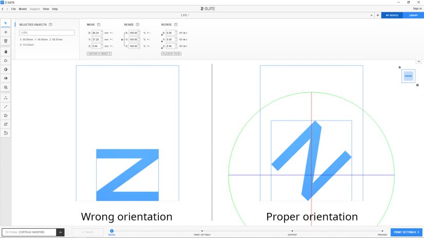
Therefore, the first thing that you have to do after you upload a file to Z-SUITE is to find the best orientation for your model to avoid having a failed print. Each layer that will be parallel to the platform has to be as small as possible to be printed successfully. That’s why a model with big and flat surfaces should be arranged on the platform at an angle. While orienting a model, pay attention to its section in the Z-axis and look for the smallest area possible. If the model has flat areas within its structure, make sure that these areas are arranged at an angle, too. Use the Rotate option in the toolbar on the left to change the model’s orientation in the workspace. To rotate the model in one or more axes, use the control grips marked red, blue and green.
Apart from arranging flat surfaces at an angle in the X or Y axis, it is advisable to arrange the model at a certain distance above the platform. Use the Move option to lift the model in the Z axis. In this way, the model will not be printed directly on the platform but on supports and raft (5mm is the default height).
By reorienting and lifting the model, you will provide better adhesion to the platform and the support structures, and it will be less likely for that part to detach from the platform and fall into the resin tank. Also, model removal will be much easier. If you print several models with the same FEP film, place your models in different spots of the platform to extend the FEP film’s lifespan.
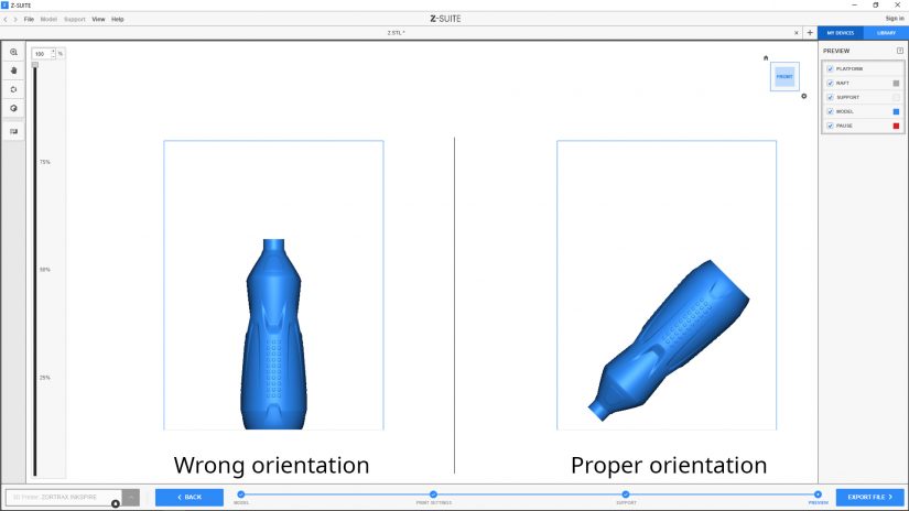
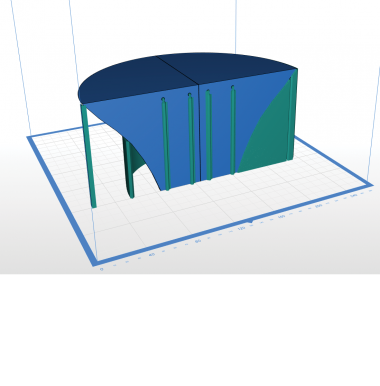
1. Models that are hollow, for example a bottle, require special orientation as well. At first, lift the model in the Z axis, arrange it at an angle and make sure that the area with the bottle’s opening faces the platform. Avoid orientation with "suction cups" (wrong orientation in the graphic) which could damage both the FEP film and the print. Also, it is still advisable to redesign the model in CAD software and create a hole in its structure. In the case of the bottle, it’s best to add it on the corner of the bottle’s base - the part that will be printed as the last one. In this way, liquid resin will drain from the whole structure into the resin tank.
1. Models that are hollow, for example a bottle, require special orientation as well. At first, lift the model in the Z axis, arrange it at an angle and make sure that the area with the bottle’s opening faces the platform. Avoid orientation with "suction cups" (wrong orientation in the graphic) which could damage both the FEP film and the print. Also, it is still advisable to redesign the model in CAD software and create a hole in its structure. In the case of the bottle, it’s best to add it on the corner of the bottle’s base - the part that will be printed as the last one. In this way, liquid resin will drain from the whole structure into the resin tank.
2. If, however, your model is hollow inside but it does not have any holes, consider redesigning it in CAD software. If it is possible for the model’s functionality and aesthetics, create a hole in its structure so that uncured resin will flow out of the model during the printing process.
Supports
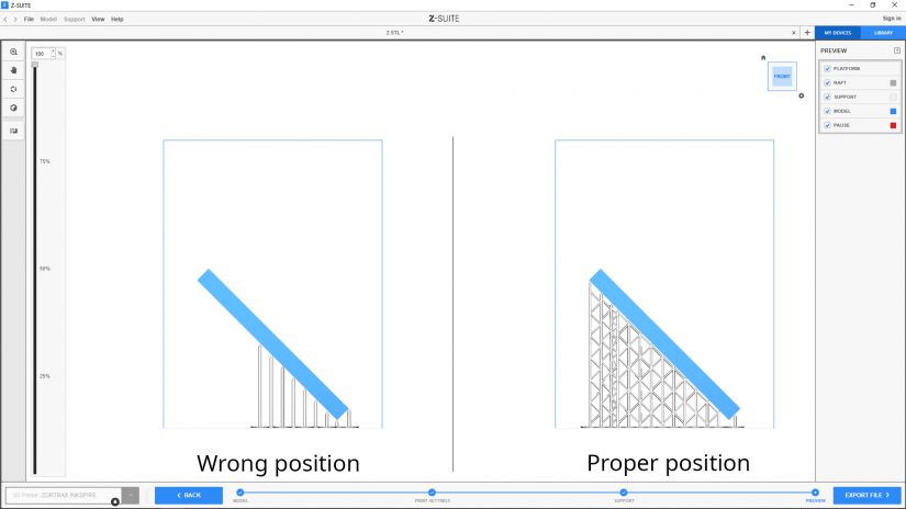
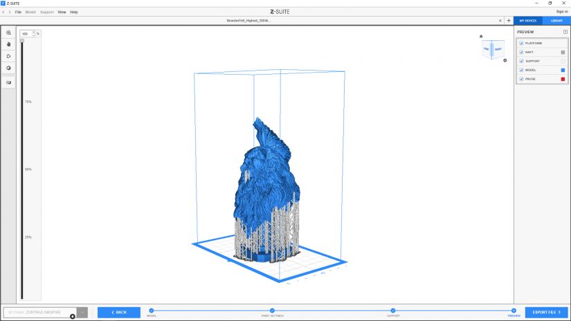
Another important step you have to make while preparing a model in Z-SUITE is to add support structures. Adequate support is essential in the upside down printing process because the model has to properly adhere to the platform and keep its original shape. Also, support has to carry the weight of the printed part so it does not collapse into the tank. Support structures for Inkspire models resemble thin pillars that end with small tips. Two or more pillars can be further reinforced with additional cross support.
There are two ways in which you can generate support structures for your model. You can either use the Automatic support option or add supports manually in the Add support menu. However, to ensure the best possible results, use both these options. Generate support automatically and evaluate its position in the preview. Check if the most important elements of your model are supported properly, and add more support or delete some of the pillars. More tips for generating supports are described later in this manual.
When using the Automatic Support option, determine the spacing between individual pillars (smaller values add more pillars), choose pillar size (use thinner pillars to support details) and tip size (tips should constitute 65% of the pillar thickness), and click Generate.
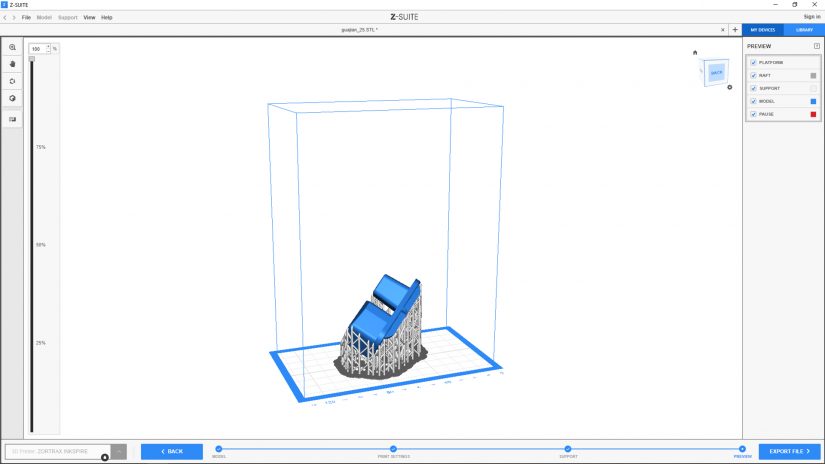
1. If you decide to use the Add support option, add pillars to all angled edges of the model or overhanging details, including those within the structure of the project. Also, add supports to a bridge structure in your model, including its highest and lowest point. Depending on the size and weight of the model, add two or three pillars close to one another so that it will be easier to add cross support. Longer pillars have to be always reinforced with additional cross support.
The position and number of support structures depend on the model’s application. Each model has to be individually evaluated in terms of adding support. In the case of technical models with complex geometries, it is important to acquire as high dimensional accuracy as possible, therefore, you have to support all the edges (including those in openings).
2. In the case of models with organic shapes, support all areas with overhanging details.


