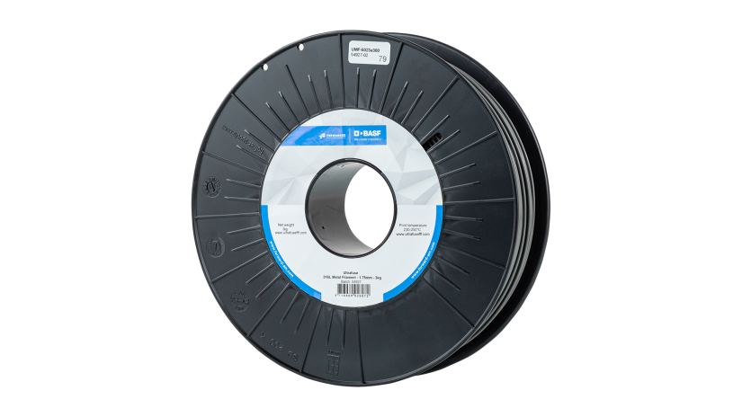
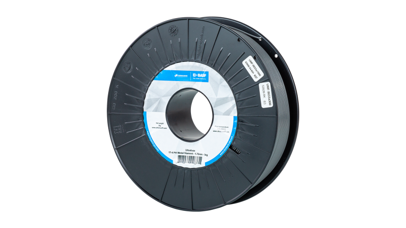
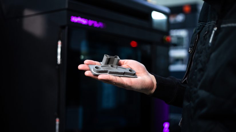
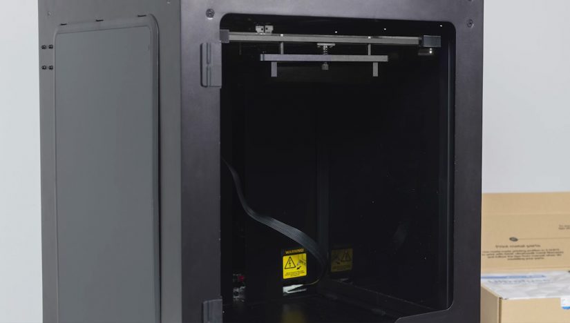
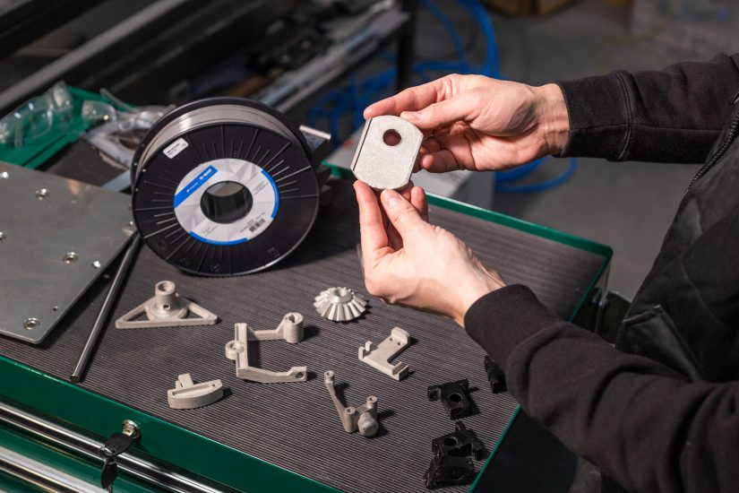
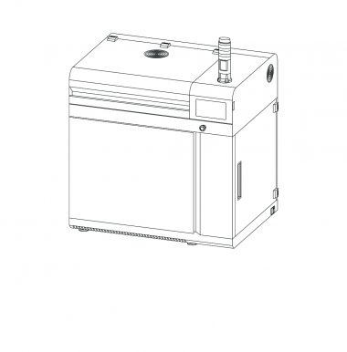
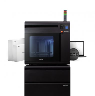
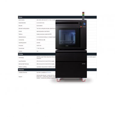
BASF Ultrafuse® 316L and BASF Ultrafuse® 17-4 PH are industrial-grade, metal-polymer composite filaments compatible with the LPD Plus Zortrax M300 Dual and Zortrax Endureal 3D printer. The filaments can be used for 3D printing industrial-grade, stainless steel components, such as elements of tooling, jigs, or parts intended for grinding, welding, drilling or sterilization. The 3D printed parts gain their metal-like properties, such as high mechanical strength, hardness, UV and temperature resistance, once they’re post-processed in a proprietary catalytic debinding and sintering process, outsourced at Elnik Systems GmbH.
This manual provides detailed guidelines on the use of BASF Ultrafuse® 316L and BASF Ultrafuse® 17-4 PH. The article is divided into sections that discuss: 3D modeling, preparing models in Z-SUITE, 3D printing, as well as preparing 3D prints for post-processing.
BASF Ultrafuse® 316L and BASF Ultrafuse® 17-4 PH Comparison
BASF Ultrafuse® 316L and BASF Ultrafuse® 17-4 PH filaments contain two most commonly used types of steel powders: 316 surgical-grade stainless steel and 17-4 PH hardened steel, respectively. Thanks to low carbon content, the 316L type is highly resistant to corrosion, but is relatively soft. The 17-4 PH type contains more carbon and is treated through the precipitation hardening method, which leads to high tensile strength and high hardness.
The 316L type has austenitic microstructure (non-magnetic), whereas the 17-4 PH type has martensitic microstructure (magnetic).
Parts 3D printed with both filaments are isotropic, and can easily be welded, polished, sterilized, or machined.
Storage:
Both BASF Ultrafuse® 316L and BASF Ultrafuse® 17-4 PH filaments should be stored at temperatures between 15 and 25 °C in original packaging. The storage area should be clean and dry. If the recommended storage conditions are observed, the filaments have up to 12 months of shelf life.
more information about:
BASF Ultrafuse® 316L
BASF Ultrafuse® 17-4 PH
Comparision
3D Modeling Guidelines
1. Parts’ Measurements
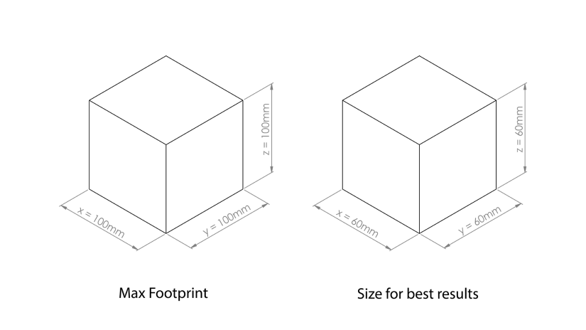
Due to the size of ceramic plates that support 3D prints during the post-processing stage, the maximum measurements for green parts are 100 x 100 x 100 mm (3.93 x 3.93 x 3.93 in). In the case of larger parts, it is necessary to make special arrangements with the provider of the post-processing services. However, it should be noted that larger parts may be prone to warpage.
The recommended measurements to achieve the best 3D printing results are: 60 x 60 x 60 mm (2.36 x 2.36 x 2.36 in).
2. Shrinkage
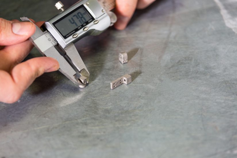
Parts 3D printed with BASF Ultrafuse® 316L and BASF Ultrafuse® 17-4 PH shrink by about 20% in the Z axis and by about 16% in the X and Y axes during the post-processing procedures.
This effect should be taken into account during the 3D modeling stage and models should be scaled up accordingly.
1. Parts’ Measurements
Due to the size of ceramic plates that support 3D prints during the post-processing stage, the maximum measurements for green parts are 100 x 100 x 100 mm (3.93 x 3.93 x 3.93 in). In the case of larger parts, it is necessary to make special arrangements with the provider of the post-processing services. However, it should be noted that larger parts may be prone to warpage.
The recommended measurements to achieve the best 3D printing results are: 60 x 60 x 60 mm (2.36 x 2.36 x 2.36 in).
2. Shrinkage
Parts 3D printed with BASF Ultrafuse® 316L and BASF Ultrafuse® 17-4 PH shrink by about 20% in the Z axis and by about 16% in the X and Y axes during the post-processing procedures.
This effect should be taken into account during the 3D modeling stage and models should be scaled up accordingly.
3. Unsupported Walls
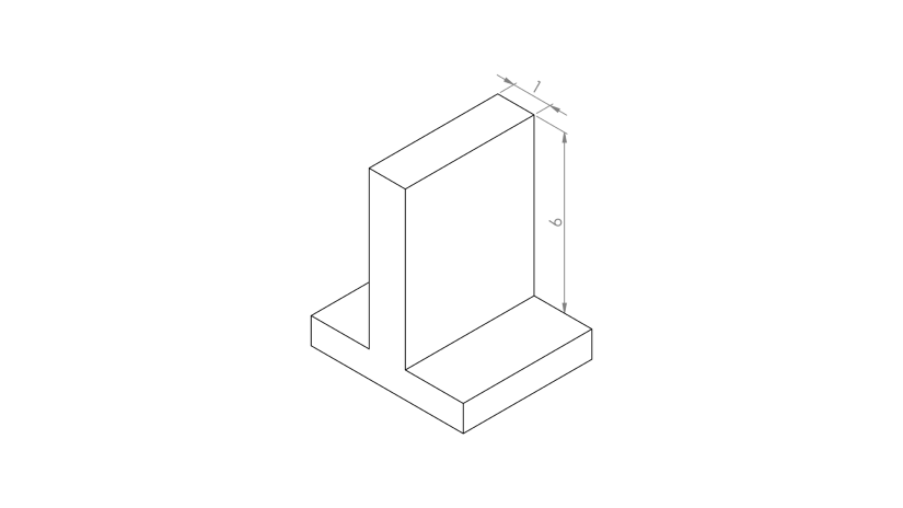
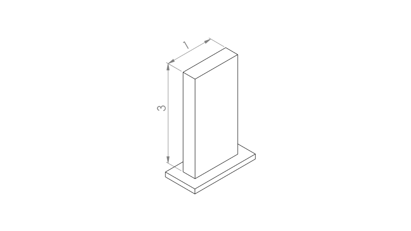
All unsupported walls in parts should be designed with height to width ratio of below 6:1 (see the graphic on the right). Walls with ratio above 6:1 will crack or collapse.
1. Height to Width Ratio
To prevent the 3D models from collapsing during the printing process or becoming distorted during the post-processing stage, it is recommended to design parts with the height to width ratio of 3:1 (see the graphic on the right). Also, it is recommended to ensure that the parts have flat bottom surfaces to reduce the possibility of distortion.
2. Wall Thickness
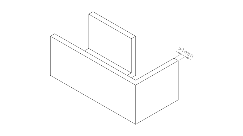
The minimum wall thickness in projects is 1 mm (0.03 in). Walls thinner than 1 mm (0.03 in) will become distorted during the post-processing stage.

3. Fillets/Chamfers
During the post-processing, green parts are subject to thermal stresses which may cause layer delamination or cracking. Projects with notches and sharp edges are especially prone to the layer separation effect. That’s why it is recommended to add fillets or chamfers in the designs.
1. Height to Width Ratio
To prevent the 3D models from collapsing during the printing process or becoming distorted during the post-processing stage, it is recommended to design parts with the height to width ratio of 3:1 (see the graphic on the right). Also, it is recommended to ensure that the parts have flat bottom surfaces to reduce the possibility of distortion.
2. Wall Thickness
The minimum wall thickness in projects is 1 mm (0.03 in). Walls thinner than 1 mm (0.03 in) will become distorted during the post-processing stage.
3. Fillets/Chamfers
During the post-processing, green parts are subject to thermal stresses which may cause layer delamination or cracking. Projects with notches and sharp edges are especially prone to the layer separation effect. That’s why it is recommended to add fillets or chamfers in the designs.
Z-SUITE Preparation
1. Models’ Orientation
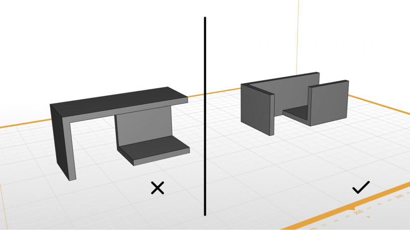
Models’ proper orientation on the platform can affect the accuracy, durability, and stability during the debinding and sintering steps. That’s why the parts should be oriented so that as many flat surfaces as possible are in contact with the platform.
2. Autoscaling
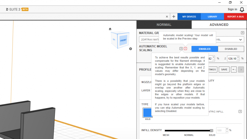
To achieve the best results possible and compensate for the shrinkage, it is suggested to enable the Automatic model scaling option in Z-SUITE. If you have scaled your models before, you can skip this step by selecting Disabled.
Also, there is a possibility that your models might go beyond the platform edges or overlap one another after using the Automatic scaling option, especially when they are close to the edges or other models. If that happens, it is recommended to reposition the models on the platform.
3. Support Angle
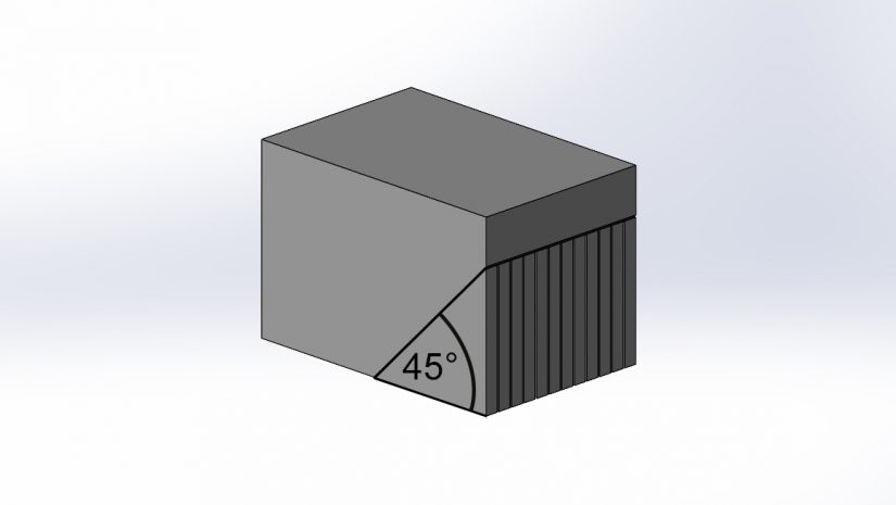
When 3D printing with BASF Ultrafuse® filaments, it is recommended to set a greater amount of supports compared to standard thermoplastics. Use supports with overhang angles under 45° (see the graphic). However, it is best to design parts so that they do not require a large number of support structures.
1. Models’ Orientation
Models’ proper orientation on the platform can affect the accuracy, durability, and stability during the debinding and sintering steps. That’s why the parts should be oriented so that as many flat surfaces as possible are in contact with the platform.
2. Autoscaling
To achieve the best results possible and compensate for the shrinkage, it is suggested to enable the Automatic model scaling option in Z-SUITE. If you have scaled your models before, you can skip this step by selecting Disabled.
Also, there is a possibility that your models might go beyond the platform edges or overlap one another after using the Automatic scaling option, especially when they are close to the edges or other models. If that happens, it is recommended to reposition the models on the platform.
3. Support Angle
When 3D printing with BASF Ultrafuse® filaments, it is recommended to set a greater amount of supports compared to standard thermoplastics. Use supports with overhang angles under 45° (see the graphic). However, it is best to design parts so that they do not require a large number of support structures.
3D Printing Guidelines for Endureal
2. Applying adhesive
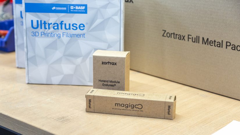
To increase models’ adhesion during the printing process, evenly apply a thin layer of Magigoo® Pro Metal on the surface of the platform.
3. Starting the printing process
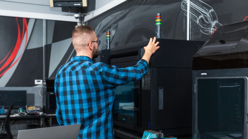
Use Wi-Fi or a USB drive to transfer the file from your computer to the printer. Start the printing process using the options from the menu.
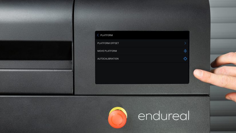
1. Platform calibration
Make sure the platform has been properly calibrated.
2. Applying adhesive
To increase models’ adhesion during the printing process, evenly apply a thin layer of Magigoo® Pro Metal on the surface of the platform.
3. Starting the printing process
Use Wi-Fi or a USB drive to transfer the file from your computer to the printer. Start the printing process using the options from the menu.
4. Removing prints from the platform
Make sure that the prints have cooled down before you remove them from the platform. Removing the prints should be carried out very carefully so as not to damage the bottom layers.
3D Printing Guidelines for M300 Dual
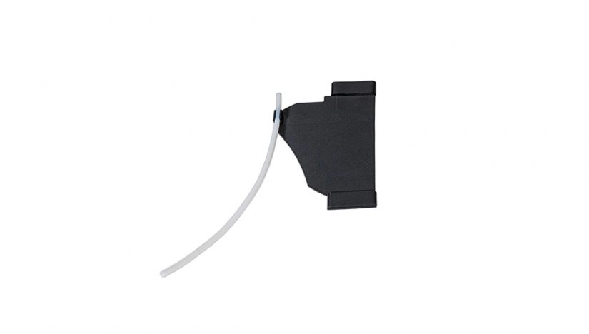
1. Install the adapter with the PTFE tube in the printer's housing according to the instructions. Make sure that the extruder cable and the PTFE tube have all necessary fixtures and are connected at a right angle.
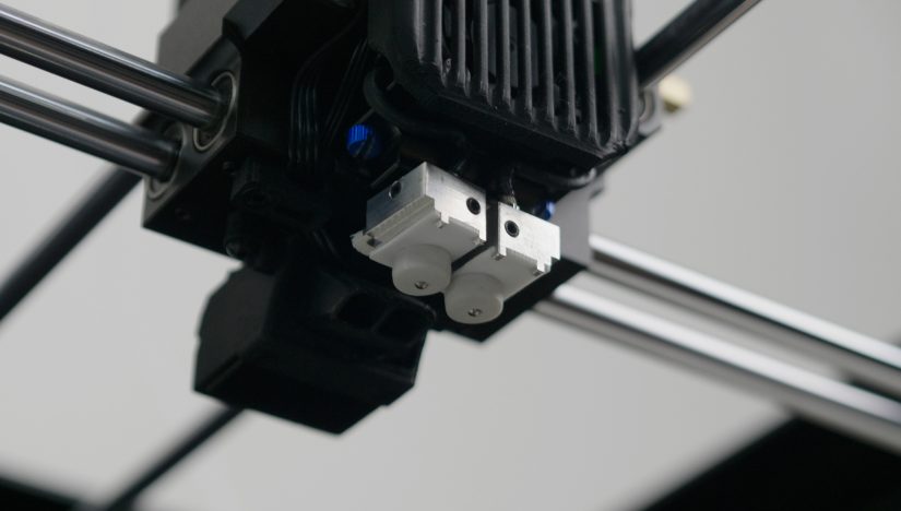
2. Install the dedicated hotend module with steel nozzles 0.4 mm. After installation, carry out the nozzle alignment.
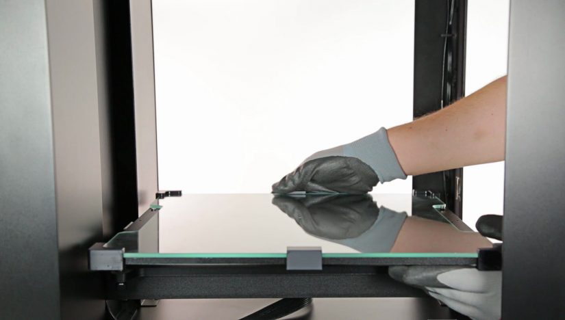
3. Install the glass plate on the heatbed. Next, carry out platform autocalibration and apply Magigoo Pro Metal adhesive onto the plate.
1. Install the adapter with the PTFE tube in the printer's housing according to the instructions. Make sure that the extruder cable and the PTFE tube have all necessary fixtures and are connected at a right angle.
2. Install the dedicated hotend module with steel nozzles 0.4 mm. After installation, carry out the nozzle alignment.
3. Install the glass plate on the heatbed. Next, carry out platform autocalibration and apply Magigoo Pro Metal adhesive onto the plate.
4. Make sure that there are no metal particles in the printer's chamber at all times. Pay special attention to the area around the heatbed cable socket, as metal remains may cause short circuit.
How to use Zortrax Full Metal Package
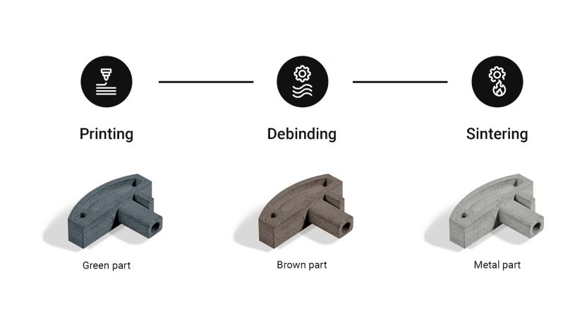
Before being post-processed, 3D prints made with BASF Ultrafuse® 316L and BASF Ultrafuse® 17-4 PH, are called “green parts” which contain metallic powder and polymeric filler in them. After the first stage of post-processing, that is debinding, such prints are called “brown parts” and they no longer contain the polymeric filler. Next, after sintering, which is the last step of the whole procedure, you obtain fully metal “white parts.”
How to Order Post-Processing Services
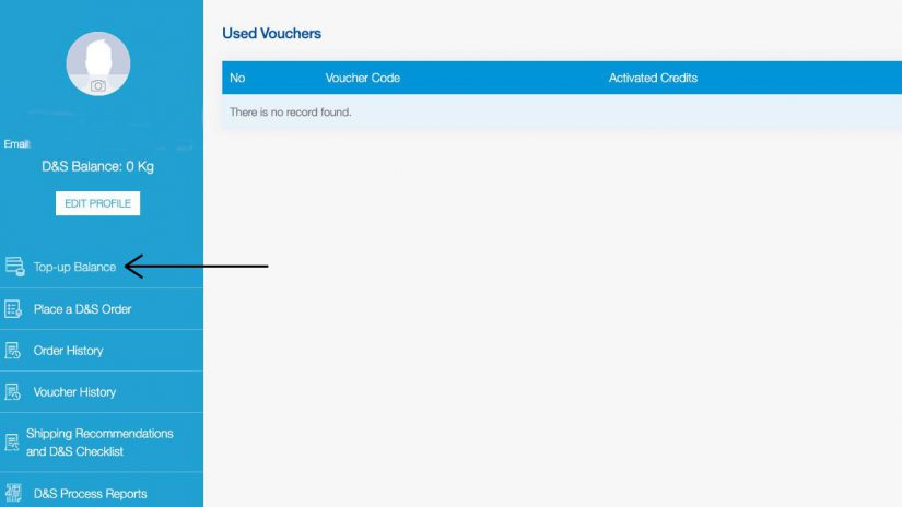
2. Once you log into your account, top it up with the code from the Voucher. Use the “Top up Balance” option. The Voucher is included in each Zortrax Full Metal Package or as a separate product.
NOTE: The Voucher does not apply for a specific amount of “green parts”, but for a specific weight - 0.5 kg. In addition, the voucher is “single-use” which means it can be used only for 1 process. The Voucher expires once it has been used.
Online via the BASF Forward AM website: https://forward-am.com/partners/debinding-and-sintering-order-managementportal (for customers from the European Union countries).
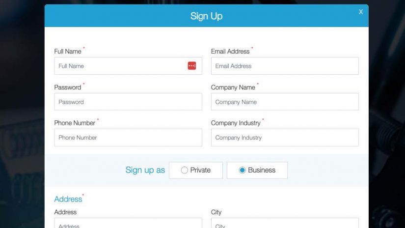
1. To send "green parts” for debinding and sintering, create your account on the website.
2. Once you log into your account, top it up with the code from the Voucher. Use the “Top up Balance” option. The Voucher is included in each Zortrax Full Metal Package or as a separate product.
NOTE: The Voucher does not apply for a specific amount of “green parts”, but for a specific weight - 0.5 kg. In addition, the voucher is “single-use” which means it can be used only for 1 process. The Voucher expires once it has been used.
3. Place an order at the website by selecting the correct material. Next, fill out the available form.
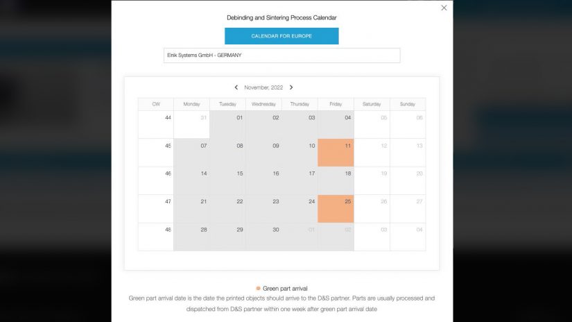
1. Select the shipment date from the calendar. Confirm or add an additional address for the return shipment.
NOTE: Debinding and sintering procedures take place every other week on Tuesday. However, the elements for the process must be delivered to the facility no later than the previous Friday. If the shipment does not reach Elnik Systems GmbH before the start date of the process, it will be stored and the services will be performed at the next date.
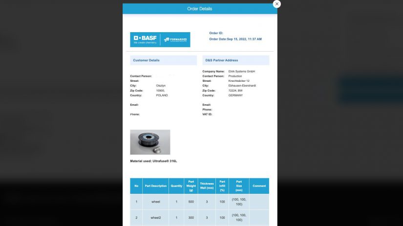
2. Once you fill out the order form and select the date of the delivery to Elnik Systems GmbH, print out the form and include it in your package with the parts.
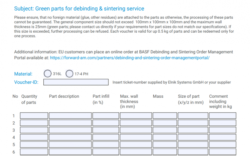
1. Download the editable order form at: link and fill it out.
NOTE: The Voucher does not apply for a specific amount of “green parts”, but for a specific weight - 0.5 kg. In addition, the voucher is “single-use” which means it can be used only for 1 process. The Voucher expires once it has been used.
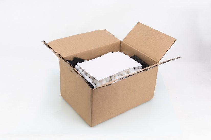
2. Once you fill out the order form, print out the form, and include it in your package with the parts. Send the package to Elnik Systems GmbH.
NOTE: The Voucher does not include the costs of return shipping for the countries outside the EU. In this case, you must provide the tracking number on the order form (if you have a signed contract with the transport company) or attach a prepaid return label to the package.
Via the form available at: (for customers from the EU countries and other countries where Zortrax Full Metal Package is available)
1. Download the editable order form at: link and fill it out.
NOTE: The Voucher does not apply for a specific amount of “green parts”, but for a specific weight - 0.5 kg. In addition, the voucher is “single-use” which means it can be used only for 1 process. The Voucher expires once it has been used.
2. Once you fill out the order form, print out the form, and include it in your package with the parts. Send the package to Elnik Systems GmbH.
NOTE: The Voucher does not include the costs of return shipping for the countries outside the EU. In this case, you must provide the tracking number on the order form (if you have a signed contract with the transport company) or attach a prepaid return label to the package.
How to Pack and Send “Green Parts” for Post-Processing
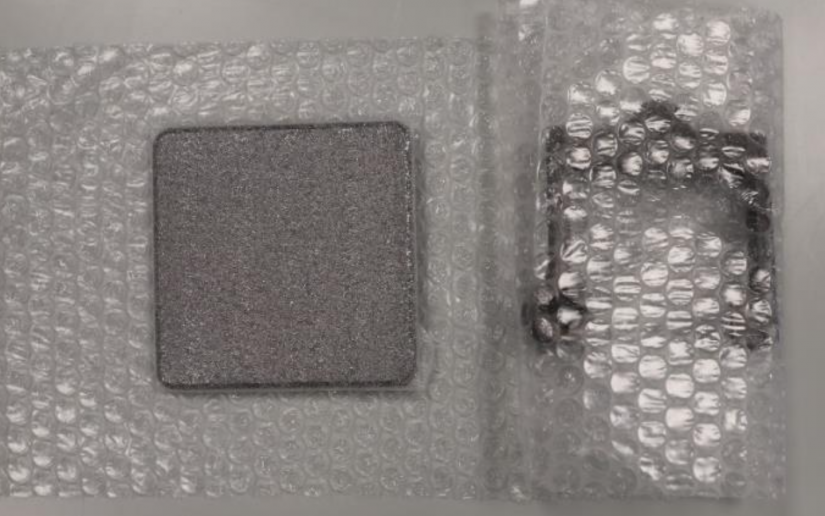
1. Packing individual prints
“Green parts” parts printed with BASF Ultrafuse® metal filaments are brittle. Therefore, special care must be taken when packing them for post-processing. We strongly recommend packing “green parts” individually in bubble wrap, foam, or other cushioning material. Make sure that each “green part” is fully wrapped and effectively packed.
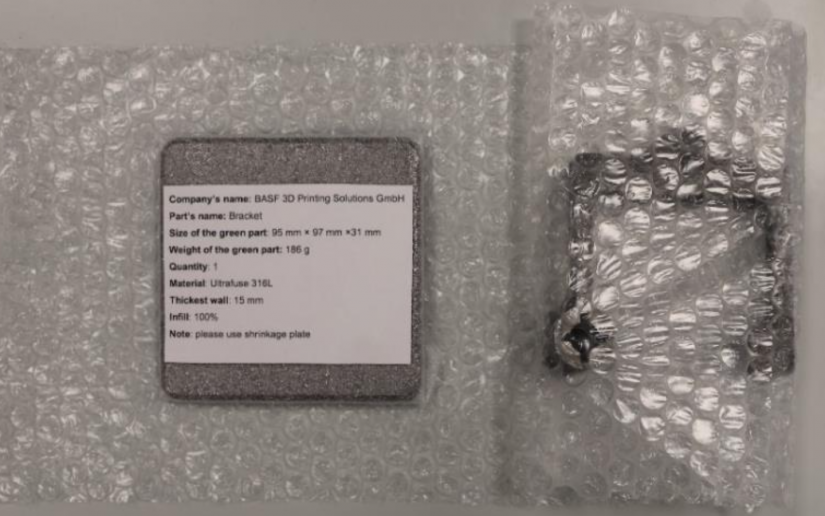
2. Labeling the parts
It is important to clearly mark all “green parts” so that they can be identified at the post-processing facility. We recommend enclosing a printed label or a written note. Add the Customer Order Details in a printed form so that the package and the parts can be easily identified.
The labels must include the following information:
Customer’s name
Part’s name
Size of the green part (x, y, z)
Weight of the green part
Quantity (in case of tensile bars)
Material (Ultrafuse 316L or Ultrafuse 17-4PH)
Thickest wall
Infill in percentage
If needed, a note (e.g. use the enclosed shrinkage plate or support structures)
1. Packing individual prints
“Green parts” parts printed with BASF Ultrafuse® metal filaments are brittle. Therefore, special care must be taken when packing them for post-processing. We strongly recommend packing “green parts” individually in bubble wrap, foam, or other cushioning material. Make sure that each “green part” is fully wrapped and effectively packed.
2. Labeling the parts
It is important to clearly mark all “green parts” so that they can be identified at the post-processing facility. We recommend enclosing a printed label or a written note. Add the Customer Order Details in a printed form so that the package and the parts can be easily identified.
The labels must include the following information:
Customer’s name
Part’s name
Size of the green part (x, y, z)
Weight of the green part
Quantity (in case of tensile bars)
Material (Ultrafuse 316L or Ultrafuse 17-4PH)
Thickest wall
Infill in percentage
If needed, a note (e.g. use the enclosed shrinkage plate or support structures)
1. Filling the packaging
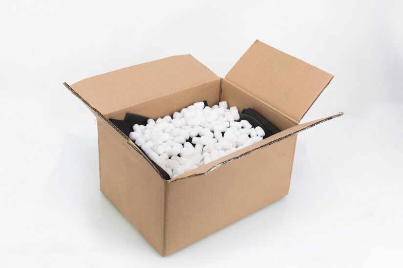
Fill all the gaps in the box with packing peanuts, styrofoam pieces, and air cushion.
2. Closing the package
Put the completed the Customer Order Details document in the package and safely secure the box - seal all joins and edges.

