Extruder maintenance is required when the printer keeps entering the Pause mode due to material jams in the extruder material ducts. It is indicated by the errors: Material jam in hotend A and Material jam in hotend B. Sometimes material residues that remain on the extruder motor sprocket wheel can make it impossible or more difficult for the printer to load materials. Also, if your printer has extrusion problems during the printing process and you notice lower quality of prints, for example there are material deficiencies on them, the extruder needs maintenance work. Follow the steps from this manual to properly disassemble the extruder and clean it from material residues.
Unloading the Materials

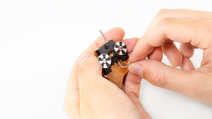
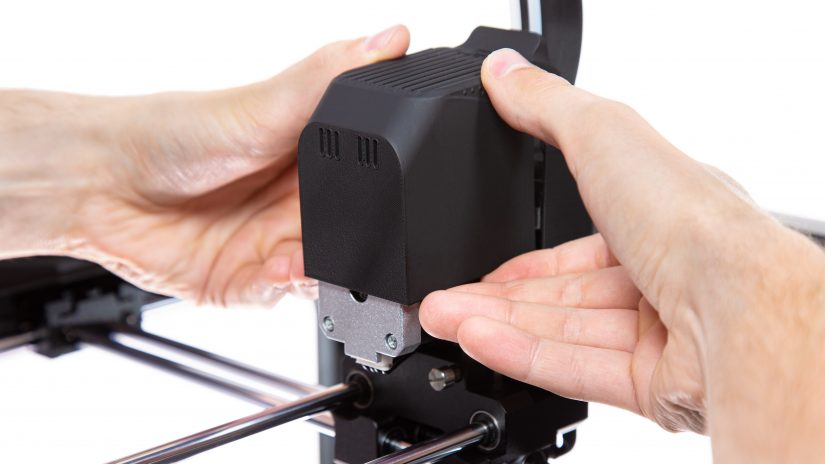
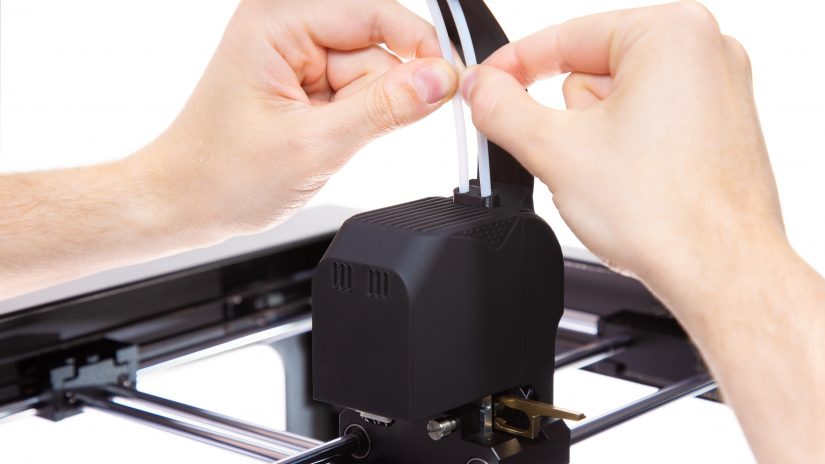
Unload both materials with the options from the menu; open the Tools menu, then choose which material you want to unload first and select the Unload material option. Unload the other material in the same way. Detach both material guides from the extruder cover. Next, turn the printer off and unplug the power cable.


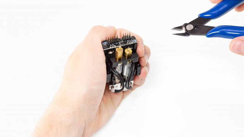
Unplugging Cables from Extruder PCB

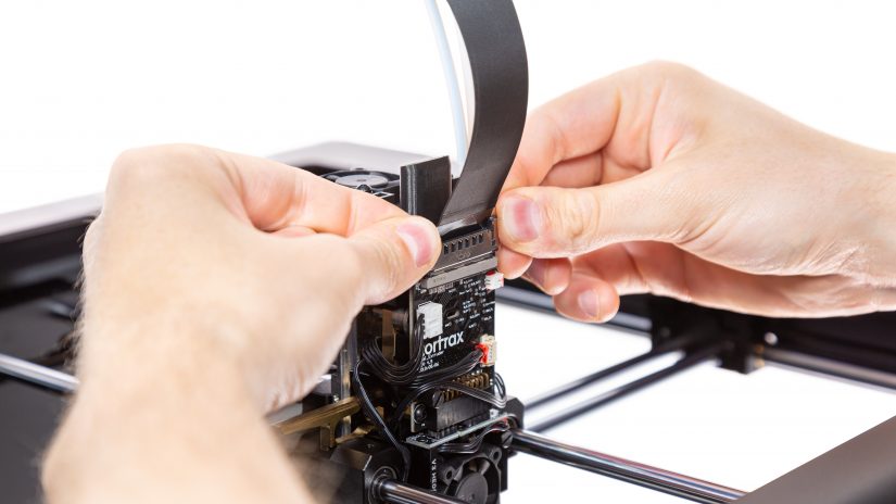
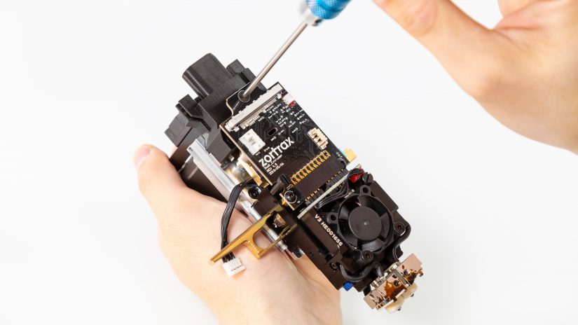
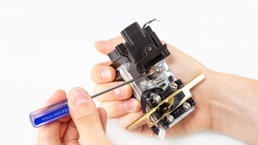
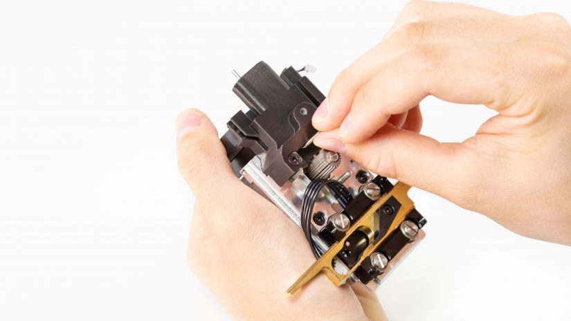
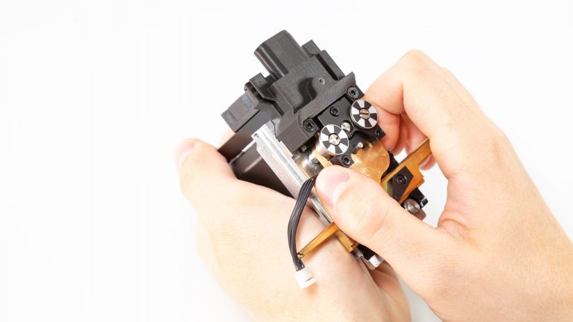
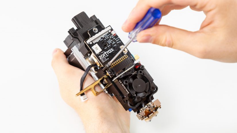
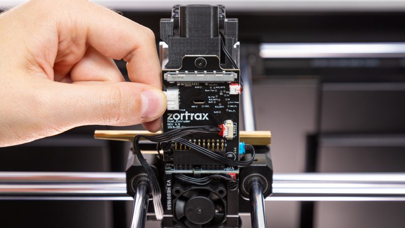
1. Unplug the extruder motor cable (the big white connector in the upper left-hand corner of the PCB).
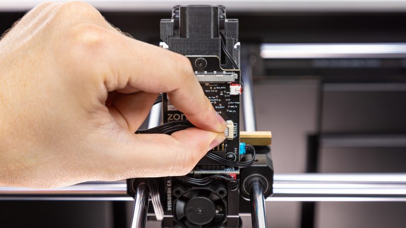
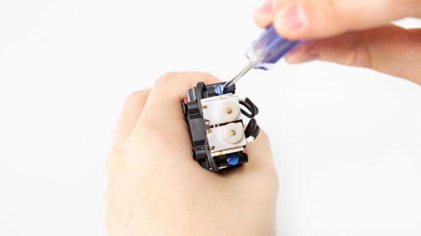
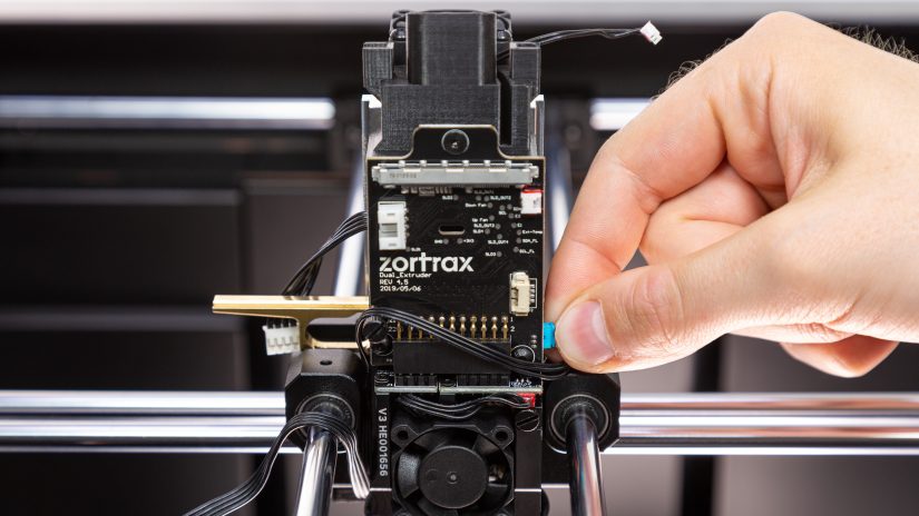
2. Unplug the capacitive sensor cable (the beige connector in the bottom right-hand corner of the PCB).

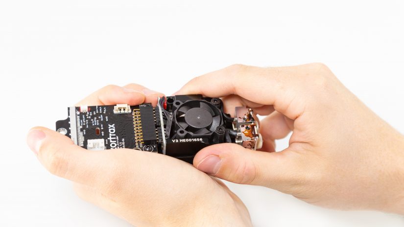
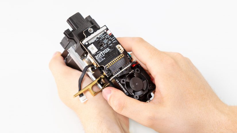
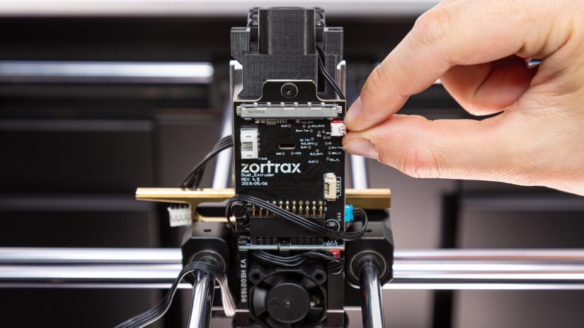
3. Unplug the upper fan cable (the small white connector in the upper right-hand corner of the PCB).

1. Unplug the extruder motor cable (the big white connector in the upper left-hand corner of the PCB).
2. Unplug the capacitive sensor cable (the beige connector in the bottom right-hand corner of the PCB).
3. Unplug the upper fan cable (the small white connector in the upper right-hand corner of the PCB).
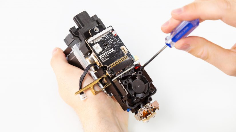
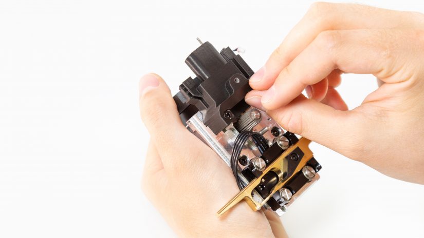
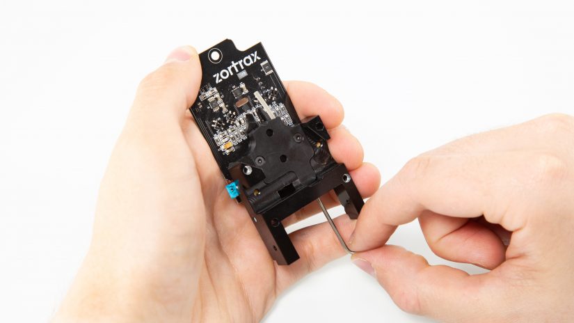
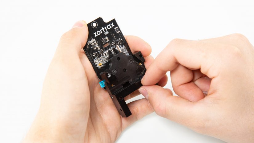
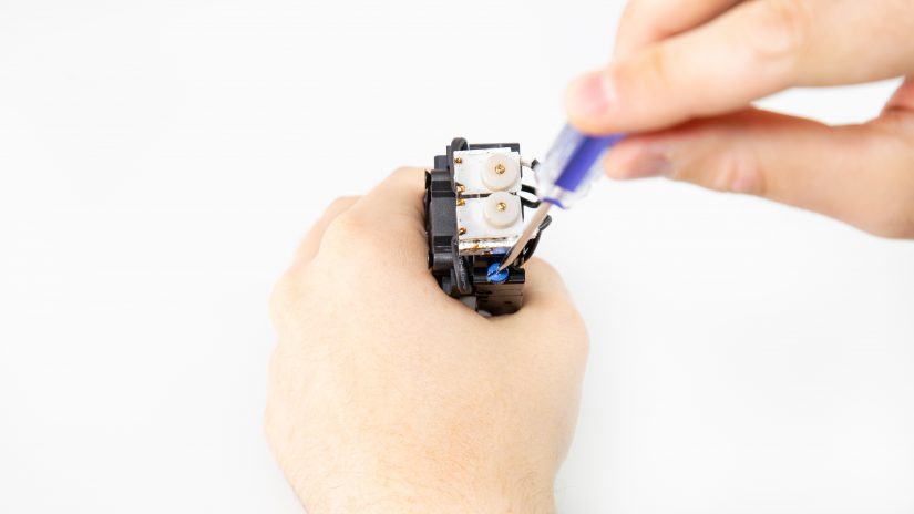
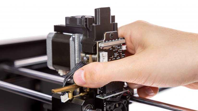
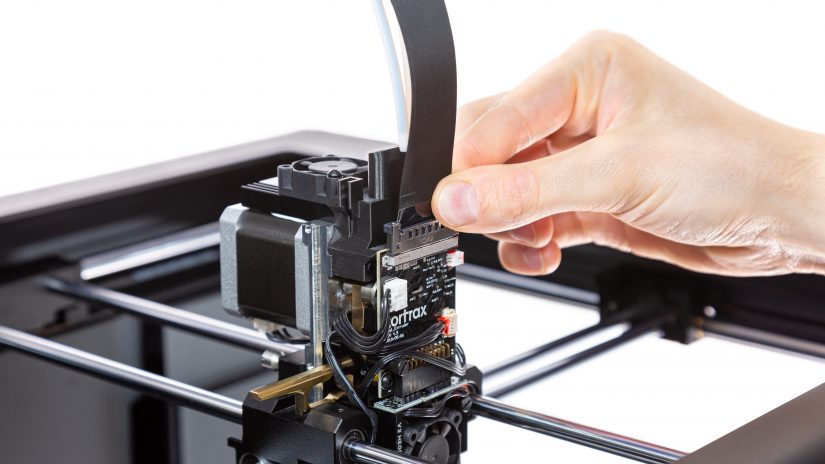
4. Unplug the bottom fan cable (the blue connector in the bottom right-hand corner of the PCB).


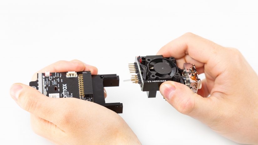


Plugging Cables into Extruder PCB
2. Plug the upper fan cable in (the small white connector in the upper right-hand corner of the PCB).

3. Plug the capacitive sensor cable in (the beige connector in the bottom right-hand corner of the PCB).
1. Plug the bottom fan cable in (the blue connector in the bottom right-hand corner of the PCB).
2. Plug the upper fan cable in (the small white connector in the upper right-hand corner of the PCB).
3. Plug the capacitive sensor cable in (the beige connector in the bottom right-hand corner of the PCB).
4. Unplug the extruder motor cable (the big white connector in the upper left-hand corner of the PCB).

