The extruder motor is responsible for loading the material into the hotend before and during the printing process. Sometimes residues that remain on the motor sprocket wheel can make it impossible or more difficult for the motor to load the material. If your printer has problems with extrusion, or you can hear a clicking sound coming from the extruder motor when you load the material or print, or if the material gets blocked in the duct in the extruder, the extruder needs maintenance work. This manual gives instructions on extruder motor sprocket wheel cleaning.
| The following manual shows the M200 maintenance work. For the M300, these procedures are the same. |
Unloading the Material
From the menu choose Material and then Unload the material option. The extruder should start to heat up automatically. Once the extruder is hot, the motor will start to unload the material.
Unplugging the Power Cable
Turn off the printer and unplug the power cable.
Material Guide Removal
Detach the material guide from the extruder cover. Next, separate the guide from the extruder cable.
Unplugging the Extruder Cable
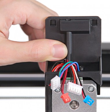
Detach the extruder upper printed cover and unplug the extruder cable.
Unplugging all Cables from the Extruder PCB
Unplug all the cables from the extruder PCB.
Unscrewing the Extruder PCB
Unscrew the two screws that secure the extruder PCB using a 2mm Allen key. Remove the PCB from the extruder.
Extruder Lower Printed Cover Removal
Remove the extruder lower printed cover.
Unscrewing the Extruder Aluminum Cover
Unscrew the screws that secure the extruder aluminum cover on both sides of the extruder. Separate the cover from the extruder motor.
Unscrewing the Extruder Motor
Unscrew the four screws that secure the extruder motor.
Extruder Motor Removal
Separate the extruder motor from the extruder block.
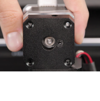
Cleaning the Sprocket Wheel
Clean the extruder motor sprocket wheel from material remains using tweezers.
Extruder Motor Assembly, part 1
Reattach the extruder motor to the extruder block.
Extruder Motor Assembly, part 2
Secure the motor with the screws. Press the motor to the right side so that the bearing rack is as close to the bearing as possible. Tighten the screws crosswise in the following order: 1-4, 2-3.
Extruder Aluminum Cover Assembly
Reattach the extruder aluminum cover to the extruder and secure it with the screws.
Extruder Lower Printed Cover Assembly
Attach the extruder lower printed cover to the extruder.
Extruder PCB Assembly
Place the extruder PCB in its place and secure it with the two screws.
Plugging all Cables to the Extruder PCB
Plug all the cables in. Remember to arrange the cables so that they don’t get damaged, e.g. by wrapping against each other.
Plugging the Extruder Cable
Plug the extruder cable in, and then attach the extruder upper cover to the lower cover.
Material Guide Installation
Attach the material guide to the extruder cover. Next, secure the guide to the extruder cable with the material guide clamps.
Plugging the Power Cable
Plug the power cable in.