The extruder is equipped with two fans – upper and lower. The main role of the extruder upper fan is to cool down the extruder, whereas the extruder lower fan cools down each layer of the print. Therefore, if your model warps, melts, or you can notice burn marks on its surface, you should check the extruder fans for proper operation. The following manual presents how to replace both extruder fans.
| The following manual shows the M200 repair work. For the M300, these procedures are the same. |
Unloading the Material
From the menu choose Material and then Unload the material option. The extruder should start to heat up automatically. Once the extruder is hot, the motor will start to unload the material.
Unplugging the Power Cable
Turn off the printer and unplug the power cable. Wait about 15 minutes and let the machine cool down.
Material Guide Removal
Detach the material guide from the extruder cover. Next, separate the guide from the extruder cable.
Unplugging the Extruder Cable
Detach the extruder upper printed cover and unplug the extruder cable.
Hotend Removal
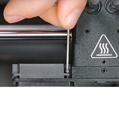
With a 1.5mm Allen key loosen the two screws that secure the hotend and remove the hotend from the extruder.
Heater and Thermocouple Removal (from the Hotend)
With a 1.5mm Allen key loosen the two screws that secure the heater and thermocouple in the hotend. Then remove the heater and thermocouple.
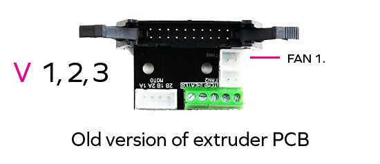
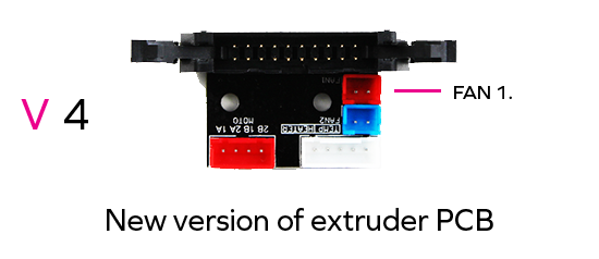
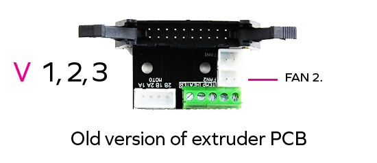
Unplugging all Cables from the Extruder PCB
Unplug all the cables from the extruder PCB.
Unscrewing the Extruder PCB
Unscrew the two screws that secure the extruder PCB using a 2mm Allen key. Remove the PCB from the extruder.
Extruder Lower Printed Cover Removal
Remove the extruder lower printed cover.
Heater and Thermocouple Removal (from the Extruder)
Remove the heater and thermocouple from the extruder block and from the heat shrink tubing. Unplug the cables from the extruder PCB.
Extruder Upper Fan Replacement
The following steps present the extruder upper fan replacement (Fan 1). It is placed on the heat sink next to the extruder alumium block. The fan grid is placed on the extruder upper fan.
Extruder Upper Fan Cable Removal
Remove the extruder upper fan cable (with the red connector) from the heat shrink tubing.
Unscrewing the Extruder Upper Fan
Unscrew the four screws that secure the extruder upper fan and remove them.
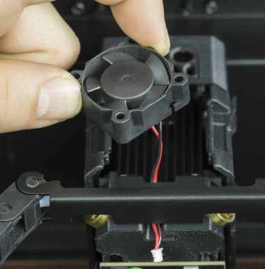
Extruder Upper Fan Removal
Remove the extruder upper fan grid and then remove the fan.
Extruder Upper Fan Assembly, part 1
Place the extruder upper fan on the heat sink next to the extruder alumium block. Next, place the grid on the fan.
Securing the Extruder Upper Fan
Secure the extruder upper fan with the four screws.
Extruder Upper Fan Assembly, part 2
Put the extruder upper fan cable through the heat shrink tubing.
Extruder Lower Fan Replacement
The following steps present the extruder lower fan replacement (Fan 2). It is placed under the heat sink next to the extruder alumium block. The fan shroud is secured to the extruder lower fan.

Extruder Lower Fan Cable Removal
Remove the extruder lower fan cable (with the blue connector) from the heat shrink tubing.
Unscrewing the Extruder Lower Fan
Unscrew the three screws that secure the extruder lower fan.
Extruder Lower Fan Removal
Separate the extruder lower fan from the heat sink and remove the distance piece.
Unscrewing the Extruder Lower Fan Shroud
Unscrew one screw that secures the extruder lower fan shroud and separate it from the fan.
Securing the Extruder Lower Fan Shroud
Put the shroud together with the new extruder lower fan and secure the shroud with one screw.
Extruder Lower Fan Assembly, part 1
Place the distance piece on the extruder lower fan. Install the fan under the heat sink.
Securing the Extruder Lower Fan
Secure the extruder lower fan with the three screws.
Extruder Lower Fan Assembly, part 2
Put the extruder lower fan cable through the heat shrink tubing and plug it in.
Heater and Thermocouple Assembly (in the Extruder)
Put the heater and thermocouple through the heat shrink tubing. Carefully put the cables in the gap in the extruder aluminum block.
Extruder Lower Printed Cover Assembly
Attach the extruder lower printed cover to the extruder.
Extruder PCB Assembly
Place the extruder PCB in its place and secure it with the two screws.
Plugging all Cables into the Extruder PCB
Plug all the cables in. Remember to arrange the cables so that they don’t get damaged, e.g. by wrapping against each other.
Heater and the Thermocouple Assembly (in the Hotend)
Insert the heater and thermocouple into the hotend and firmly tighten the two screws that secure them (using a 1.5mm Allen key).
Make sure that the screws don’t go through the insulation that covers the wires (this can happen if the heater goes too deep into the slot).

| This picture shows the heater inserted correctly. | This picture shows the heater pushed too far into the slot in the hotend. |
Hotend Assembly
Insert the hotend into the extruder and tighten the two screws that secure it (using a 1.5mm Allen key).
Plugging the Extruder Cable
Plug the extruder cable in, and then attach the extruder upper cover to the lower cover.
Material Guide Installation
Attach the material guide to the extruder cover. Next, secure the guide to the extruder cable with the material guide clamps.
Plugging the Power Cable
Plug the power cable in.